Lessons
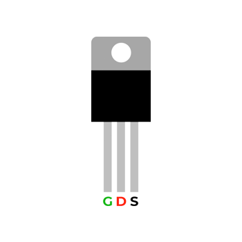
MOSFETs Lecture
Battery Removal
Lab Overview This circuit uses battery decay or battery removal to pull the gate of the MOSFET (Q1) low, allowing the capacitor to fire a single detonator. Tools / Parts / Test Equipment Soldering Iron Helping Hands Solder Multimeter
Adjustable Light Sensor
Lab Overview This circuit uses a LDR to trigger a MOSFET (Q1) to fire a single detonator. Tools / Parts / Test Equipment Soldering Iron Helping Hands Solder Multimeter
Adjustable Dark Sensor
Lab Overview This circuit uses a LDR to trigger a MOSFET (Q1) to fire a single detonator. Tools / Parts / Test Equipment Soldering Iron Helping Hands Solder Multimeter
MOSFET RC Timer
Lab Overview This circuit uses the RC timed circuit to trigger a MOSFET (Q1) to fire a single detonator. Tools / Parts / Test Equipment Soldering Iron Helping Hands Solder Multimeter
LDR Battery Removal
Lab Overview This circuit combines a Dark Sensor Circuit and a Battery Removal Circuit to fire a single detonator through a MOSFET. Tools / Parts / Test Equipment Soldering Iron Helping Hands Solder Multimeter
RC Timer Armed LDR
Lab Overview This circuit uses a capacitor and LDR to function. The capacitor/RC timer arms the device and the LDR fires the device. Tools / Parts / Test Equipment Soldering Iron Helping Hands Solder Multimeter
RC Timer Dual MOSFET
Lab Overview This circuit uses a RC Timer to arm the two MOSFETs.The gate from either MOSFETs (Q1 and Q2) fires the device. Tools / Parts / Test Equipment Soldering Iron Helping Hands Solder Multimeter
