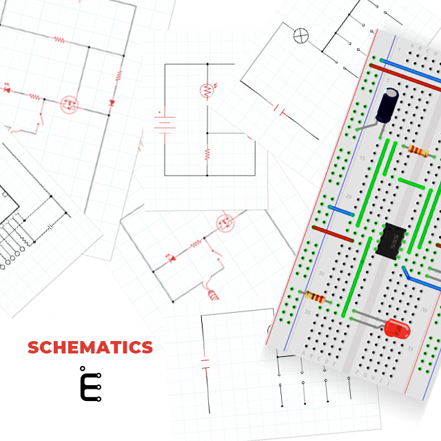
Professional Electronics
Price range: $21,500.00 through $25,000.00
Professional Electronics
Intensive 5-Day Circuit Analysis and Component Integration for Industry Applications
Course Overview
Professional Electronics provides comprehensive training in electronic circuit analysis, component identification, and hands-on troubleshooting for industrial, automotive, and control system applications.
Target Audience: Engineering technicians, maintenance professionals, system integrators, and technical personnel working with industrial control systems, automotive electronics, and embedded applications.
Description
5-Day Intensive Structure
Following EOD Electronics Curriculum Topics
Day 1: Technician Skills and Basic DC Electronics
Foundation Skills and DC Circuit Analysis (8 hours)
Morning Session (4 hours):
– Technician Skills: Digital multimeter operation (Fluke 101, 87V techniques)
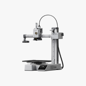
– Breadboarding: Professional prototyping and circuit construction
– Through-hole soldering: Component mounting and connection techniques
– Basic DC: Voltage, current, resistance fundamentals
Afternoon Session (4 hours):
– Units of Measurement: Volt, amp, and ohm relationships
– Basic Circuits: Series circuits and parallel circuits analysis
– Kirchhoff’s Current Law: Current distribution in circuits
– Coulomb and Electric Charge: Fundamental electrical concepts
– Ohm’s Law: How voltage, current and resistance relate
– Ohm’s Law Triangle Technique: Practical calculation methods
– Analyzing Basic Circuits with Ohm’s Law: Real-world applications
Day 2: Resistors and Capacitors
Passive Component Analysis and Applications (8 hours)
Morning Session (4 hours):
– Resistors: Component fundamentals and applications
– Types of Resistors: Fixed and variable configurations
– Variable Resistors: Potentiometers and rheostats
– Thermistor: Temperature-sensitive resistance devices
– Photoresistor/LDR: Light-dependent resistors
– Varistor Resistor: Voltage-dependent resistors
– Surface Mount Resistor: SMD identification and handling
– Applications of a Resistor: Current limiting and voltage division
– Switches (COTS): Commercial off-the-shelf switching devices
Afternoon Session (4 hours):
– Capacitors: Energy storage fundamentals
– The Capacitance of a Capacitor: Basic principles
– Standard Units of Capacitance: Farad, microfarad, picofarad
– Capacitance of a Parallel Plate Capacitor: Design calculations
– The Dielectric of a Capacitor: Insulating materials
– Voltage Rating of a Capacitor: Maximum operating voltage
– Types of Capacitors: Material and construction varieties
Day 3: Diodes and Transistors
Active Semiconductor Components (8 hours)
Morning Session (4 hours):
– Diodes: Semiconductor fundamentals and applications
– Forward and reverse bias operation
– Rectification and voltage regulation circuits
– Protection circuits and signal processing
– Transistors: Amplification and switching applications
– BJT operation and biasing techniques
– MOSFET voltage-controlled switching
– Load line analysis and operating points
Afternoon Session (4 hours):
– Actuators: Electromechanical control devices
– History/Theory: Development of electromechanical devices
– Diagram – Electric Actuator: Motor and solenoid control
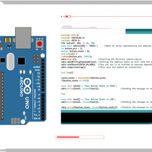
Day 4: Microcontrollers and Sensors with Arduino
Comprehensive Arduino Integration and Sensor Systems (8 hours)
Morning Session (4 hours):
– Arduino Fundamentals and Setup: Introduction to Arduino ecosystem
– Arduino Uno board architecture and pinout
– Digital I/O pins, analog inputs, PWM outputs
– Power supply options and voltage regulators
– Arduino IDE installation and configuration
– Building Arduino on Breadboard: ATmega328P microcontroller setup
– Crystal oscillator and timing circuits
– Reset circuit and programming interface
– Power supply decoupling and filtering
– Programming Essentials: Basic sketch structure
– Digital input/output operations
– Analog-to-digital conversion (ADC)
– Pulse Width Modulation (PWM) control
– Serial communication for debugging
Afternoon Session (4 hours):
– Digital Sensor Interfacing: Push buttons and mechanical switches
– PIR motion sensors
– Ultrasonic distance sensors (HC-SR04)
– Reed switches and Hall effect sensors
– Rotary encoders for position sensing
– Analog Sensor Integration: Temperature sensors (TMP36, thermistors)
– Light sensors (photoresistors, photodiodes)
– Potentiometers for user input
– Current and voltage sensing modules
– Signal conditioning and filtering
– Advanced Sensor Systems: I2C communication protocol and devices
– SPI communication for high-speed sensors
– ToF LIDAR distance measurement
– Accelerometers and gyroscopes
– Environmental sensors (humidity, pressure)
– Actuator Control: LED and LED strip control
– Relay modules for high-power switching
– Servo motor positioning
– DC motor control with H-bridges
– Stepper motor precision control
Day 5: Diagnostics and Troubleshooting with Fluke Meter
Professional Testing Procedures and Six-Step Troubleshooting Method (8 hours)
Morning Session (4 hours):
– Fluke Multimeter Mastery: Model comparison (Fluke 101 vs 87V)
– Safety ratings and CAT categories
– Proper probe selection and usage
– Min/Max recording and data logging
– True RMS vs average responding meters
– Advanced Measurement Techniques: Voltage measurements in live circuits
– Current measurement using clamp meters
– Resistance and continuity testing
– Capacitance and frequency measurements
– Diode and transistor testing modes
– Temperature measurements with thermocouples
– Specialized Testing Functions: Ghost voltage identification
– Burden voltage considerations
– Input impedance effects
– Relative mode measurements
– Peak hold and transient capture
Afternoon Session (4 hours):
– Six-Step Troubleshooting Method: Systematic approach to diagnostics
– Step 1 – Gather Information: Interview operators about symptoms
– Review equipment history and logs
– Document intermittent vs constant failures
– Step 2 – Understand the System: Review schematics and documentation
– Identify subsystems and signal flow
– Establish normal operating parameters
– Step 3 – Identify Possible Causes: List potential failure points
– Rank by probability
– Consider environmental factors
– Step 4 – Plan the Approach: Determine test sequence
– Select appropriate test equipment
– Identify safety considerations
– Step 5 – Test and Repair: Systematic voltage testing
– Current draw analysis
– Signal tracing techniques
– Component-level testing
– Safe component replacement
– Step 6 – Document and Follow Up: Record all measurements
– Update equipment logs
– Recommend preventive measures
– Practical Troubleshooting Exercises: Power supply diagnostics
– Sensor circuit fault finding
– Arduino system debugging
– Motor control troubleshooting
– Intermittent fault isolation
– Professional Best Practices: Safety-first approach
– Lockout/tagout procedures
– ESD protection methods
– Test equipment calibration
– Building a troubleshooting toolkit
You may also like…
Related products
-
Arduino Bootcamp for EOD
Price range: $24,768.00 through $28,990.00 Select options This product has multiple variants. The options may be chosen on the product page -
EOD Electronics
Price range: $19,250.00 through $24,650.00 Select options This product has multiple variants. The options may be chosen on the product page -
EOD Electronics IED Defeat Hybrid
Price range: $27,674.00 through $31,489.64 Select options This product has multiple variants. The options may be chosen on the product page